Layout_Design_Errors
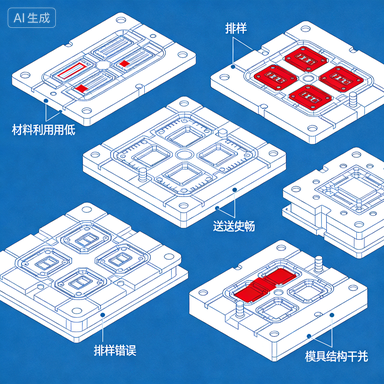
Stamping Die Design Warning: Five Types of Layout Errors Most Easily Overlooked
In the stamping die design process, layout design directly affects material utilization and production efficiency. However, many designers tend to focus too much on the die structure itself while neglecting the many problems hidden in the layout phase. This article summarizes five types of layout errors that are most easily overlooked for industry reference.
1. Unreasonable Scrap Bridge Design
Too small scrap bridges will cause material to be pulled into the die during blanking, resulting in increased burrs and accelerated die wear. Too large scrap bridges waste material and increase production costs. Experts recommend that for ordinary steel, the scrap bridge value should be 1.5-2 times the material thickness, with a minimum of 1mm. For soft materials such as aluminum alloys, the scrap bridge value should be increased to 2-2.5 times the material thickness.
2. Ignoring Material Grain Direction
The grain direction formed during sheet rolling has a significant impact on the mechanical properties of stamped parts. The bending line of bent parts should be as perpendicular to the grain direction as possible to avoid bending cracks. In actual design, some engineers arrange workpieces at arbitrary angles to pursue higher material utilization, creating hidden quality problems.
3. Feed Pitch Calculation Errors
Pitch calculation must consider pilot pin diameter, pilot clearance, and elastic elongation of the material. Common errors include: insufficient pilot allowance leading to increased cumulative errors during multi-station stamping; mismatch between pitch and feeding mechanism causing under-feeding or over-feeding.
4. Scrap Discharge Channel Design Defects
If scrap generated from blanking cannot be discharged smoothly, it is very likely to cause die jamming or workpiece damage. During design, ensure the scrap sliding angle is not less than 25°, scrap hole size should be 2-3mm larger than the scrap profile, and avoid interference between scrap falling path and other die components.
5. Not Considering Strip Stability
During narrow-long or irregular layout, the strip tends to twist or warp during feeding. Design should reasonably set carrier width and add hold-down devices or side guides when necessary to ensure smooth strip feeding.
Industry Recommendations
“Layout design seems simple but actually requires rich practical experience,” suggests a senior die designer. After design completion, a layout review should be conducted, inviting process and production departments to participate together to examine the feasibility of the plan from different angles. Meanwhile, using CAD/CAM software automatic nesting function can effectively reduce human errors and optimize material utilization.